脉冲发生器
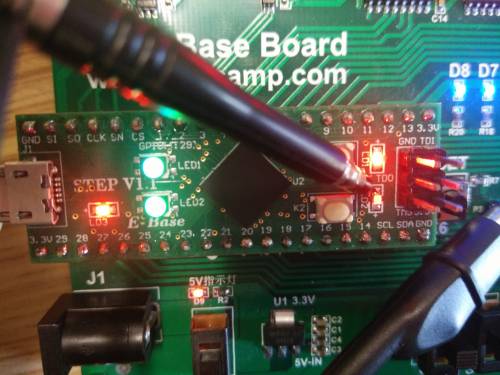
1. 硬件平台
2. 设计要求
- 掌握Verilog子模块的调用
- 掌握PWM和脉冲发生的原理
- 基于STEP-Baseboard平台实现脉冲发生器的设计,周期可调,占空比可调
3. 工作原理
脉冲发生器是信号发生器的一种,是周期和占空比均可调的矩形脉冲的发生器。
周期:在数字信号的领域中是信号变化的过程中,某段波形重复出现,其某一次开始至结束的这段时间就称为“周期“。
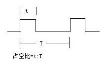
占空比:是在一串理想的脉冲系列中,正脉冲的持续时间与脉冲周期的比值。例如在下图中t为正脉冲的持续时间,T为脉冲周期,占空比为t/T。
脉冲发生一般通过对一个高频的脉冲信号进行分频来生成。
分频比:指方波的周期和高频信号周期之间发的比例关系,通过控制分频比来生成不同频率的方波。例如,开发系统上的时钟频率是25MHz,如果要生成5MHz的方波,则分频比为5。
4. 硬件连接
为了方便在硬件平台上演示,我们使用25MHz的系统时钟作为高频信号做分频处理,产生脉冲信号,通过调节脉冲信号的周期和正脉冲的宽度,最终生成我们需要的脉冲信号。
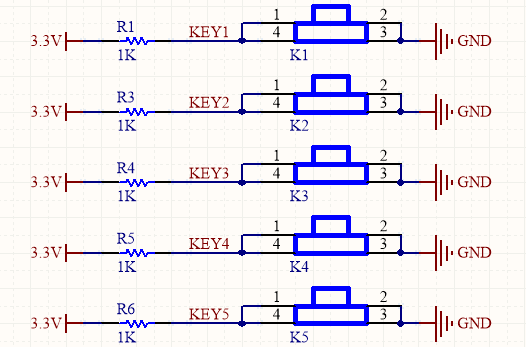
三路按键输入:
- keymenu:使用按键K5作为输入,按动K5按键控制周期和脉宽调节模式的切换。 * keyup:使用按键K1作为输入,按动K1按键根据所处的模式控制周期或脉宽参数的增加。
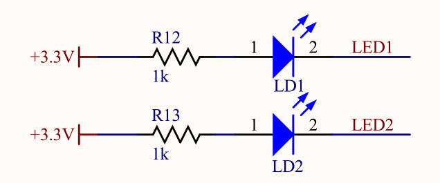
- keydown:使用按键K3作为输入,按动K3按键根据所处的模式控制周期或脉宽参数的减小。 两路LED输出: * menustate:使用小脚丫核心板上的LD1作为输出,当LED点亮或熄灭时分别表示脉宽调节模式或周期调节模式。
- pulse_out:使用小脚丫核心板上的LD2作为输出,可以根据LED的亮度表示周期和脉宽的变化(注意:当输出低电平时LED点亮)。
5. 代码设计
5.1 设计文件
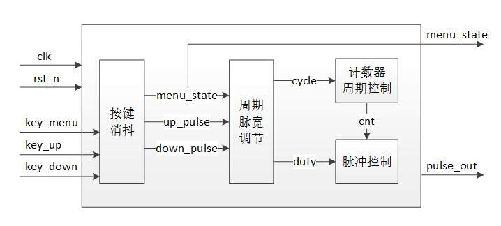
我们在硬件连接中也提到了脉冲发生器设计需要的硬件资源作为接口外设,整个设计的接口定义如下:
input			clk_in,
input			rst_n_in,
input			key_menu,
input			key_up,
input			key_down,
output			menu_state,
output	reg		pulse_out
本设计中我们用到三个按键作为输入,需要对按键输入做消抖处理,消抖模块的原理及设计请参考按键消抖设计,这里我们增加了按键输入信号的位宽,同时对三路按键输入做消抖处理 ,如下:
//Debounce for key
wire [2:0] key_state,key_pulse;
Debounce1 Debounce_uut
(
.clk(clk_in),
.rst_n(rst_n_in),
.key_n({key_menu,key_up,key_down}),
.key_state(key_state),
.key_pulse(key_pulse)
);

wire menu_state = key_state[0];
wire up_pulse = key_pulse[1];
wire down_pulse = key_pulse[2];
对三路按键做消抖后的信号可以实现周期和脉宽的控制,本设计中我们的分频比范围为2~16分级可调,0%<脉宽<100%分级可调,控制脉宽参数duty要始终小于周期参数cycle,
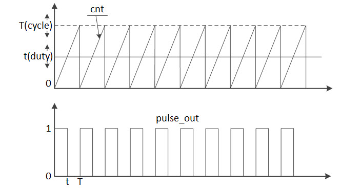 实现方法如下:
//Control cycle and duty cycle
always @(posedge clk_in or negedge rst_n_in) begin
	if(!rst_n_in) begin
		cycle<=4'd8;
		duty<=4'd4;
	end else begin
		if(menu_state) begin
			if(up_pulse && (cycle<4'd15)) cycle <= cycle + 4'd1;
			else if(down_pulse && (cycle>(duty+4'd1))) cycle <= cycle - 4'd1;
			else cycle <= cycle;
		end else begin
			if(up_pulse && (cycle>(duty+4'd1))) duty <= duty + 4'd1;
			else if(down_pulse && (duty>4'd0)) duty <= duty - 4'd1;
			else duty <= duty;
		end
	end
end
最后根据周期参数cycle控制计数器的计数范围,根据脉宽参数duty控制正电压脉冲的宽度,产生脉冲信号。
reg	[3:0]	cnt;
//counter for cycle
always @(posedge clk_in or negedge rst_n_in) begin
	if(!rst_n_in) begin
		cnt<=4'd0;
	end else begin
		if(cnt>=cycle) cnt<=4'd0;
		else cnt <= cnt + 4'd1;
	end
end

//pulse generate with duty
always @(posedge clk_in or negedge rst_n_in) begin
	if(!rst_n_in) begin
		pulse_out<=1'b1;
	end else begin
		if(cnt<=duty) pulse_out<=1'b1;
		else pulse_out<=1'b0;
	end
end
引脚分配如下:
| 管脚名称 | clkin| rstnin| keymenu | keyup|keydown | menustate|pulseout | ||||
|---|---|---|---|---|---|---|---|
| FPGA管脚 | C1 | A2 | A12 | B8 | A10 | A3 | A7 |
6. 运行结果
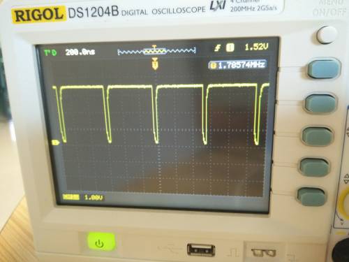
7. 资源报告
| 资源 | 数量 | 比例 | 说明 |
|---|---|---|---|
| LUTs | 65 | 5% | |
| 寄存器 | 42 | 3% | |
| 存储器 | 0 | 0% | |
| IO管脚 | 7 | ||
| 时钟频率 | 25MHz |
8. 知识点
- 按键消抖
- PWM脉宽调节
- 脉冲发生原理
9. 参考文档
10. 相关代码
10.1 脉冲发生器代码
可下载文件:脉冲发生器Top文件
// --------------------------------------------------------------------
// >>>>>>>>>>>>>>>>>>>>>>>>> COPYRIGHT NOTICE <<<<<<<<<<<<<<<<<<<<<<<<<
// --------------------------------------------------------------------
// Module: Pulse_gen
//
// Author: Step
//
// Description: Pulse generate module
//
// Web: www.ecbcamp.com
//
// --------------------------------------------------------------------
// Code Revision History :
// --------------------------------------------------------------------
// Version: |Mod. Date:   |Changes Made:
// V1.0     |2015/11/11   |Initial ver
// --------------------------------------------------------------------
module Pulse_gen
(
input					clk_in,
input					rst_n_in,
input					key_menu,
input					key_up,
input					key_down,
output					menu_state,
output	reg				pulse_out
);

//Debounce for key
wire [2:0] key_state,key_pulse;
Debounce1 Debounce_uut
(
.clk(clk_in),
.rst_n(rst_n_in),
.key_n({key_menu,key_up,key_down}),
.key_state(key_state),
.key_pulse(key_pulse)
);

wire menu_state = key_state[2];
wire up_pulse = key_pulse[1];
wire down_pulse = key_pulse[0];


reg	[3:0] cycle;
reg	[3:0] duty;
//Control cycle and duty cycle
always @(posedge clk_in or negedge rst_n_in) begin
	if(!rst_n_in) begin
		cycle<=4'd8;
		duty<=4'd4;
	end else begin
		if(menu_state) begin
			if(up_pulse && (cycle<4'd15)) cycle <= cycle + 4'd1;
			else if(down_pulse && (cycle>(duty+4'd1))) cycle <= cycle - 4'd1;
			else cycle <= cycle;
		end else begin
			if(up_pulse && (cycle>(duty+4'd1))) duty <= duty + 4'd1;
			else if(down_pulse && (duty>4'd0)) duty <= duty - 4'd1;
			else duty <= duty;
		end
	end
end

reg	[3:0]	cnt;
//counter for cycle
always @(posedge clk_in or negedge rst_n_in) begin
	if(!rst_n_in) begin
		cnt<=4'd0;
	end else begin
		if(cnt>=cycle) cnt<=4'd0;
		else cnt <= cnt + 4'd1;
	end
end

//pulse generate with duty
always @(posedge clk_in or negedge rst_n_in) begin
	if(!rst_n_in) begin
		pulse_out<=1'b1;
	end else begin
		if(cnt<=duty) pulse_out<=1'b1;
		else pulse_out<=1'b0;
	end
end

endmodule
10.2 按键消抖部分的代码
可下载代码:按键消抖设计代码
// --------------------------------------------------------------------
// >>>>>>>>>>>>>>>>>>>>>>>>> COPYRIGHT NOTICE <<<<<<<<<<<<<<<<<<<<<<<<<
// --------------------------------------------------------------------
// Module: Debounce1
//
// Author: Step
//
// Description: Debounce for button with FPGA/CPLD
//
// Web: www.ecbcamp.com
//
// --------------------------------------------------------------------
// Code Revision History :
// --------------------------------------------------------------------
// Version: |Mod. Date:   |Changes Made:
// V1.0     |2015/11/11   |Initial ver
// --------------------------------------------------------------------
module Debounce1(clk,rst_n,key_n,key_pulse,key_state);

input   				clk;			//system clock
input   				rst_n;			//system reset
input   		[2:0]	key_n;			//button input
output  		[2:0]	key_pulse;		//Debounce pulse output
output	reg		[2:0]	key_state;		//Debounce state output

reg [2:0] key_rst;
//Register key_rst, lock key_n to next clk
always @(posedge clk  or  negedge rst_n)
    if (!rst_n) key_rst <= 3'b111;
    else  key_rst <=key_n;

//Detect the edge of key_n
wire  key_an = (key_rst==key_n)? 0:1;

reg[18:0]  cnt;
//Count the number of clk when a edge of key_n is occured
always @ (posedge clk  or negedge rst_n)
    if (!rst_n) cnt <= 19'd0;
    else if(key_an) cnt <=19'd0;
    else cnt <= cnt + 1'b1;

reg [2:0] low_sw;
//Lock the status to register low_sw when cnt count to 19'd500000
always @(posedge clk  or  negedge rst_n)
    if (!rst_n)  low_sw <= 3'b111;
	else if (cnt == 19'd500000)
        low_sw <= key_n;

reg [2:0] low_sw_r;
//Register low_sw_r, lock low_sw to next clk
always @ ( posedge clk  or  negedge rst_n )
    if (!rst_n) low_sw_r <= 3'b111;
    else  low_sw_r <= low_sw;

wire [2:0] key_pulse;
//Detect the negedge of low_sw, generate pulse
assign key_pulse= low_sw_r & ( ~low_sw);

//Detect the negedge of low_sw, generate state
always @(posedge clk or negedge rst_n)
	if (!rst_n) key_state <= 3'b111;
	else if(key_pulse[0]) key_state[0] <= ~key_state[0];
	else if(key_pulse[1]) key_state[1] <= ~key_state[1];
	else if(key_pulse[2]) key_state[2] <= ~key_state[2];
	else key_state <= key_state;

endmodule
