用开关、按键控制LED的亮和灭
在本示例中加入了输入按键/开关的控制,用4个开关和4个按键来控制8个LED的亮、灭。
1. 知识点
- 控制输入的原理和构成方式
- 开关和按键的不同
- 在Verilog中用输入管脚的状态来控制输出管脚的状态
2. 原理图
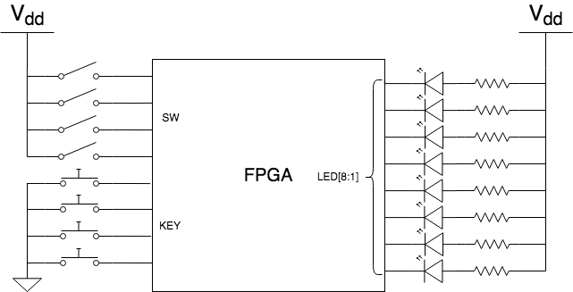
如上图中所示,为了让大家体会FPGA 输入管脚的状态,开关和按键的连接方式做了不同的配置:
- 开关的状态缺省为低电平,没有按下时,该信号线被连接的10KΩ电阻拉到地上,当开关按下时,该信号线直通3.3V的电源线,变成高电平;
- 按键的状态缺省为高电平,没有按下时,该线号线被连接的10KΩ电阻拉到3.3V电源上,当按键按下时,该信号线直通到GND,变成低电平。
3. Verilog代码
// ********************************************************************
// >>>>>>>>>>>>>>>>>>>>>>>>> COPYRIGHT NOTICE <<<<<<<<<<<<<<<<<<<<<<<<<
// ********************************************************************
// File name    : LED_onoff_sw.v
// Module name  : led_onoff_sw
// Author       : STEP
// Description  : control 8 leds on and off with 4 push buttons and 4 switchs
// Web          : www.stepfpga.com
//
// --------------------------------------------------------------------
// Code Revision History :
// --------------------------------------------------------------------
// Version: |Mod. Date:   |Changes Made:
// V1.0     |2021/09/15   |Initial ver
// --------------------------------------------------------------------
// Module Function: use external button to control leds

module LED (key,sw,led);

	input [3:0] key;			// 4 push buttons input
	input [3:0] sw;				// 4 switchs input
	output [7:0] led;			// output control signals to 8 leds

	assign led = {key,sw};                  //assign led signal values to 4 keys input + 4 switches input

endmodule
Verilog语法说明:
- 规范的代码需要对该模块进行充分的注释说明,因此在此段代码的前部,我们增加了更详细的信息 - 文件名、作者、日期、简单的描述、版本号等等,这些信息对于代码的管理和控制是非常有必要的,因此要养成良好的习惯。我们硬禾实战营在学员的培训过程中专门制定了一套代码规范 - 硬禾实战营FPGA代码规范
- 虽然使用的输入输出端口多了,代码却变简单了,这是因为用到的信号都是可以成组进行定义和操作的,比如4个按键、4个开关和8个LED,只有三种不同性质的端口,而且这三种端口之间的逻辑关系非常清晰;
- 最后的assign语句中用到了拼接符{},key的4位和sw的4位拼接在一起,映射到led的8位上。
4. 管脚分配
管脚分配如下:

将模块端口的16个信号分别分配给8个LED和4个按键、4个开关
5. 功能验证
将生成的JED文件下载到FPGA板以后的效果:
用开关和按键可以控制LED的on/Off, 正常开关和按键的状态都为高电平,8个LED都处于灭的状态,改变开关和按键的装填可以让LED亮起来,按键、开关和LED一一对应。